I suspect the brick wall would be C2 providing their code, not that anything was being infringed... Hell the company I work for doesn't have patents for our software, but we don't share the code of it.... so if anyone were to ask, it'd also be a brick wall!Slidewinder wrote: ↑May 3rd, 2023, 9:54 amWe are in agreement. My comment was a refutation of Carl Watts' suggestion that your work and Nomath's could constitute patent infringement.JaapvanE wrote: ↑May 3rd, 2023, 9:29 amIt is far from a brick wall, and nobody can legally stop anyone from..etc."Slidewinder wrote: ↑May 3rd, 2023, 9:21 amIn the 2021 thread linked by Nomath, Carl Watts advises not to delve into the black box too far because "it's C2's intellectual property and trust me that's a brick wall."
Building my own PM
Re: Building my own PM
M 6'4 born:'82
PB's
'23: HM=1:36:08.0, 60'=13,702m
'24: 10k=42:13.1, FM=3:18:35.4, 30'=7,132m
'25: 500m=1:35.3, 2k=7:39.3, 5k=20:24.3, 6k: 25:05.4
Logbook
PB's
'23: HM=1:36:08.0, 60'=13,702m
'24: 10k=42:13.1, FM=3:18:35.4, 30'=7,132m
'25: 500m=1:35.3, 2k=7:39.3, 5k=20:24.3, 6k: 25:05.4
Logbook
-
Carl Watts

- Marathon Poster
- Posts: 4720
- Joined: January 8th, 2010, 4:35 pm
- Location: NEW ZEALAND
Re: Building my own PM
Concept 2 will not even provide a full electrical schematic for the 1996 PM2 monitor when pretty much any university electrical student can reverse engineer the board and come up with that if you have the time so there is ZERO chance of getting any code.
I even contemplated completely redesigning the board at one point because the layout is terrible.
I even contemplated completely redesigning the board at one point because the layout is terrible.
Carl Watts.
Age:56 Weight: 108kg Height:183cm
Concept 2 Monitor Service Technician & indoor rower.
http://log.concept2.com/profile/863525/log
Age:56 Weight: 108kg Height:183cm
Concept 2 Monitor Service Technician & indoor rower.
http://log.concept2.com/profile/863525/log
Re: Building my own PM
So I have been thinking about the resource issue and the high frequency impulses and recently I fund out that one of the Kayak Ergometers I use (KayakFirst) tackled this approach in a rather interesting way (they do not use the regression model in their calculation, I believe they used the below described approach to provide flexibility on the software update side, as it is easier to update a program on a host device, like phone, than on an MCU).
So basically they use BLE UART Serial profile (or they emulate serial over BLE) to broadcast serial messages to a host device that does the calculation and all processing (in their case its a mobile phone). Basically a UART interface is emulated via BLE. Since BLE can have a throughput in the ranges of Mbits I think this could be a feasible options for low CPU application, i.e. having a host program on a PC or somewhere that does the processing while the ESP (or any other) chip you have can do some basic filtering and calculate the delta times and send them to the connected host device.
Also this is a much simpler solution for everyone that is not that familiar with embedded system programming (especially the tooling...), as one can technically create a nodeJS application (even repurpose ORMs GPIO service) to read the serial messages sent via BLE.
Actually this could open up quite a few possibilities since if there is a USB Serial chip on dev board, technically the same thing could be done over USB. This would potentially allow a basic 20mhz chip (like an ATiny) without Bluetooth to take advantage of advanced calculations.
What needs to be done is ORM's GPIO service needs to be changed in a way that instead of setting up and running the Rpi GPIOs it starts a serial monitor and reads the stdout of that command line by line and processes it. This would provide a rather simple solution (and can be done with the ESP chip you have) on the coding part. Of course there will be some edge cases that needs testing like what if the serial is late and you get multiple lines, how do you process those etc. but this is way simpler than setting up code from scratch.
Re: Building my own PM
PM5 supposedly uses STM32F4xx chips (at least according to them: https://www.updesigns.com/portfolio-ite ... -monitors/), I would assume the one with the dedicated LCD controller. They also use separate NordicSemi NRF chips for the BLE and ANT communication.Carl Watts wrote: ↑May 2nd, 2023, 5:38 pmThe Concept 2 PM2 only uses a Phillips 8051 based micro, I think the crystal is 4.3Mhz, had to replace them a few times but never actually measured the frequency.
Re: Building my own PM
In essence the Java-version of ORM does the same thing, although in a software-only approach. The high accuracy stuff is offloaded to a software library incredibly close to the hardware (JS version of pigpio, which calls the C-based high-frequency pigpio library), running at a high prio, and as long as you get accurate timestamps, any delay further down the line wouldn't matter as it is all timestamped.Abasz wrote: ↑May 11th, 2023, 4:06 amSo basically they use BLE UART Serial profile (or they emulate serial over BLE) to broadcast serial messages to a host device that does the calculation and all processing (in their case its a mobile phone). Basically a UART interface is emulated via BLE. Since BLE can have a throughput in the ranges of Mbits I think this could be a feasible options for low CPU application, i.e. having a host program on a PC or somewhere that does the processing while the ESP (or any other) chip you have can do some basic filtering and calculate the delta times and send them to the connected host device.
So you either get a stream of timestamps, or a series of delta's. As long as the measuring device is accurate, it wouldn't matter.
That was in fact one of the fallback scenario's for ORM, if GPIO polling proved to be too inaccurate. We also found similar solutions that actually worked that way: register data on the ESP/Arduino and do some initial processing there to make data less time sensitive, and let the Raspberry Pi do the heavy lifting for the much less time-critical data analysis and presentation. I even found industrial boards that had both in a single compact package (for industrial applications).Abasz wrote: ↑May 11th, 2023, 4:06 amAlso this is a much simpler solution for everyone that is not that familiar with embedded system programming (especially the tooling...), as one can technically create a nodeJS application (even repurpose ORMs GPIO service) to read the serial messages sent via BLE.
Actually this could open up quite a few possibilities since if there is a USB Serial chip on dev board, technically the same thing could be done over USB. This would potentially allow a basic 20mhz chip (like an ATiny) without Bluetooth to take advantage of advanced calculations.
What needs to be done is ORM's GPIO service needs to be changed in a way that instead of setting up and running the Rpi GPIOs it starts a serial monitor and reads the stdout of that command line by line and processes it. This would provide a rather simple solution (and can be done with the ESP chip you have) on the coding part. Of course there will be some edge cases that needs testing like what if the serial is late and you get multiple lines, how do you process those etc. but this is way simpler than setting up code from scratch.
I agree with you that ORM is now at a point where a lot is offered out of the box functionality is so interesting (HR measuring, BLE and ANT+ broadcast to connect to games, tcx and RowingData export) that it would be much smarter to modify existing code instead of building one's own from scratch.
I think that the cheapest solution would be a Raspberry Pi Zero 2W, but I haven't had the time to order one and play with it.
Package maintainer of OpenRowingMonitor, the open source Rowing Monitor
-
Daniele_Redivo
- Paddler
- Posts: 8
- Joined: April 30th, 2023, 6:00 pm
Re: Building my own PM
hello again,
more results using ESP8266 with CPU running at 80MHz.
I have been working on the calculations of the drag factor. To do this I detect first the start of recovery phase and then I calculate the points (xi, yi) at each blade passage. xi is the time from the start of recovery, yi is the time between consecutive blades. First I checked that (xi,yi) plot on a line with the same slope regardless of the force I apply, but depending on the amount of air bled through the wheel cover.
Then I implemented the linear regression according to: https://www.colorado.edu/amath/sites/de ... ch12_0.pdf
I optimized a bit the calculation, so that it is carried through all the recovery phase and not all at once at the end. This leads to smaller peaks of CPU load. For ex. I do the summing of the xi, yi, xi*yi, xi^2 at every interrput, so that when the recovery phase is done, the CPU only needs to do a 2 or 3 multiplications, 3 divisions and 2 additions.
xi is calculated by micros()/100. yi is calculated by micros(). Drag factor is multiplied by 1000 to get reasonable values. Using model B I get a drag between 150 (vent fully closed) and 180 (vent fully open). The drag is quite stable. With vent fully closed it oscillates between 149 and 152.
Next steps are to calcualted other quantities like speed, power, and so on.
-
Daniele_Redivo
- Paddler
- Posts: 8
- Joined: April 30th, 2023, 6:00 pm
Re: Building my own PM
What I still have doubts about is how to calculate the speed. I found this formula:
u = ( k / c )^(1/3) ω (9.2)
from here: http://eodg.atm.ox.ac.uk/user/dudhia/ro ... ter.html#w
but I cannot figure out what unit u has. I 'd like then to convert it to min/500m.
The link above does not say how to compute ω. I assumed that ω cannot be instantaneous angular speed, otherwise I'd get a jumping speed all the time. I picked the average flywheel speed of each stroke as ω. So I divide flywheel rotations during a stroke by the period of each stroke and then multiply by ( k / c )^(1/3).
What other approaches to speed calculations would you suggest?
Re: Building my own PM
I admire the tenacity to stick to your own data acquisition and processing!Daniele_Redivo wrote: ↑May 12th, 2023, 6:08 amWhat I still have doubts about is how to calculate the speed. ...
Regarding the formula you took from Dudia, keep in mind that the factor k is proportional to the drag factor but not equal to that factor. A drag factor of 150 means that in kg-m-s units the value of k is 150*10^(-6) kg.m².
The value of c is even more problematic. It will include the moment of inertia of the flywheel (0.100 kg.m²) but also some arbitrary C2 constant ("202.5 W average power over one stroke equals a linear speed of 4.17 m/s").
But the key simplification that you want to apply is to take ω as the number of flywheel rotations during a stroke divided by the period of a stroke. There should be at least a factor 2*pi to convert from rps to radians/second. If properly measured, ω varies continuously during a stroke. In the power calculation ω is raised to the third power, so high values of ω contribute much more than low values to the momentary power input.
Moreover, the measurement of the rotation period will incur a lot of random noise. The figure below shows my own measurement of the rotation period from the C2 sensor during one stroke in the start-up phase. I used a rather sophisticated method to determine the maximum of each sensor pulse AND applied strong digital smoothing filters to reduce the noise. Still there is considerable noise visible in the figure. My guess is that more crudely processed data are much more noisy. I am not sure what this means to your estimated average ω values and eventually to the estimated linear speed. If you have those unprocessed ω (or rotation speed) data as a function of time available, I would like to see them.

Re: Building my own PM
Interesting, as it might explain some data. Do you have a source for this data?
Please confirm if you are measuring this on a D/RowErg with new magnet setup, as that behaves fundamentally different then a Model B with its 3 magnet setup (which is the subject here).
Aside that, our measurements show that the thing you call "random noise" on a RowErg is not random at all. Far from it, it is a very systematic (probably deliberately designed) magnet configuration that creates a sinoid inside a full flywheel rotation. We measured several flywheel across several countries, machines in different ages, and even brand new replacement flywheels, all 6 magnet flywheels have the exact same sinoid. So it isn't random at all, it is very systematic for new machines.
As we measured with 1us precission with various circuits, I'm quite confident this isn't a product of electronics or measurement inaccuracy.
That is not the recommended approach for this type of noisy data. Running average filters with this type of deviation does not result in a stable result unless you are essentially killing the key signal. As an important part of the data is not only the angular velocity but also angular acceleration, a (running average?) smoothing filter will interfere too much. Running median filters are more effective, but given the presence of a systematic error combined with a upward or downward trend, also not useable.Nomath wrote: ↑May 12th, 2023, 4:37 pmThe figure below shows my own measurement of the rotation period from the C2 sensor during one stroke in the start-up phase. I used a rather sophisticated method to determine the maximum of each sensor pulse AND applied strong digital smoothing filters to reduce the noise. Still there is considerable noise visible in the figure. My guess is that more crudely processed data are much more noisy.
I tested this on around 2000K of rowing data, and angular velocity can be made relatively stable with some occasional glitches with a running median of 12 datapoints and a forward extrapolating predictive algorithm. But stroke detection will remain problematic as the 2nd derivative function (angular acceleration) remains chaotic and can't be controlled, which is a key ingredient for that algorithm. Although we have applied extremely complex noise reduction algorithms, with predictive algorithms to fix misplaced datapoints, in essence it is the road to hell as you are tackling the problem with the wrong tools. Configuration of the algorithms is extremely fragile and a nightmare to set up, and a small error will lead to missed strokes.
For in-situ measurement sliding regression analysis or a Fourier transformation are the textbook approaches (although the typical cyclic nature of the rowing stroke with its unpowered period might be frustrating fourier transformation in-situ) as they are designed to handle misplaced datapoints.
For the RowErg on ORM we use debounce filter of 50us (although the RowErg doesn't seem to need it) and apply quadratic Theil-Senn regression with a minimum of two full rotations as there is a structural cyclic deviation in the signal. This algorithm is much more robust, allows sloppy configuration and provides a very stable 2nd derived function, allowing strike detection to be robust as well, and even provide force curves.
Thanks for confirming that your flywheel has the same issues as the rest of the field.
Package maintainer of OpenRowingMonitor, the open source Rowing Monitor
-
Daniele_Redivo
- Paddler
- Posts: 8
- Joined: April 30th, 2023, 6:00 pm
Re: Building my own PM
hello, thanks for your answers. It's an interesting topic.
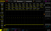
Here are the requested shapes of the signal sent out from the sensor. As I wrote earlier, my model B didn't come with any sensor or magnet. I added an inductive switch which detects the passage of the blades (8 per turn), see my older posts for the pictures. I feed the sensor with more than 30V. Lower voltages limited its frequency response. The sensor output is very clean (no noise) and the amplitude is always about 24-25V regardless of the wheel speed. This makes all the signals processing much easier compared to standard Hall effect or reed sensors, I think.
156Hz sensors output:
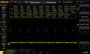
63Hz sensors output:
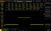
very low Hz sensors output:
Here are the requested shapes of the signal sent out from the sensor. As I wrote earlier, my model B didn't come with any sensor or magnet. I added an inductive switch which detects the passage of the blades (8 per turn), see my older posts for the pictures. I feed the sensor with more than 30V. Lower voltages limited its frequency response. The sensor output is very clean (no noise) and the amplitude is always about 24-25V regardless of the wheel speed. This makes all the signals processing much easier compared to standard Hall effect or reed sensors, I think.
156Hz sensors output:
63Hz sensors output:
very low Hz sensors output:
Re: Building my own PM
I am not going to reply your post because I think a discussion about the technical issues raised in it don't help the topic poster.JaapvanE wrote: ↑May 12th, 2023, 7:04 pm...
Interesting, as it might explain some data. Do you have a source for this data?
....
Please confirm if you are measuring this on a D/RowErg with new magnet setup, as that behaves fundamentally different then a Model B with its 3 magnet setup (which is the subject here).
.....
That is not the recommended approach for this type of noisy data. Running average filters with this type of deviation does not result in a stable result unless you are essentially killing the key signal.
......
Aside that, our measurements show that the thing you call "random noise" on a RowErg is not random at all. Far from it, it is a very systematic (probably deliberately designed) magnet configuration that creates a sinoid inside a full flywheel rotation. We measured several flywheel across several countries, machines in different ages, and even brand new replacement flywheels, all 6 magnet flywheels have the exact same sinoid. So it isn't random at all, it is very systematic for new machines.
....
For the RowErg on ORM we use debounce filter of 50us (although the RowErg doesn't seem to need it) and apply quadratic Theil-Senn regression with a minimum of two full rotations as there is a structural cyclic deviation in the signal. This algorithm is much more robust, allows sloppy configuration and provides a very stable 2nd derived function, allowing strike detection to be robust as well, and even provide force curves.
.....
Thanks for confirming that your flywheel has the same issues as the rest of the field.
You are making all kind of assumptions, e.g. that I was using a running average filter, which are mostly wrong. It reads like a condescending lecture about signal processing.
Re: Building my own PM
Very interesting, but these are not the graphs I like to see. I like to see a graph of ω (radial velocity) versus time or of Tr (rotation period) versus time, for one or two strokes to see the capability of your sensing method and data processing.Daniele_Redivo wrote: ↑May 13th, 2023, 11:18 amhello, thanks for your answers. It's an interesting topic.
Here are the requested shapes of the signal sent out from the sensor. As I wrote earlier, my model B didn't come with any sensor or magnet. I added an inductive switch which detects the passage of the blades (8 per turn), see my older posts for the pictures.
....
There is something alarming in what you wrote previously :
I have never seen a real model B. From earlier topics, e.g. here, I know that the drag is higher than for the models C/D, and drag factors in the range 80-200 as for model C/D are only possible with special covers over the flywheel cage. Note that in kg-m-s units this equals a drag coefficient of 80-120 * 10^(-6) kg m². You multiplied by 1000 to get a drag factor between 150 and 180, hence a drag coefficient of 150000-180000 * 10^(-6). This must be wrong by orders of magnitude !Daniele Redivo wrote: I have been working on the calculations of the drag factor.
....
Drag factor is multiplied by 1000 to get reasonable values. Using model B I get a drag between 150 (vent fully closed) and 180 (vent fully open). The drag is quite stable. With vent fully closed it oscillates between 149 and 152.
Next steps are to calcualted other quantities like speed, power, and so on.
The equation for the increase in rotation period of an air-braked flywheel when there is no input power is : d(Tr)/dt = 2π * (C/J)
C is the drag coefficient in kg m² ; J is the moment of inertia of the flywheel in kg m².
Note that the ratio C/J is a dimensionless number. This number characterizes how fast the flywheel slows down because of air drag, i.e. loses its kinetic energy. The value of J for models B/C/D is 0.100 kg m². With a typical value for C of 0.000120 kg m², the rotation period increases very slowly. This is in accordance with the observation that the flywheel keeps spinning for minutes after the last stroke.
The value of C=0.150 that you reported, implies that in one second the rotation period increases by about 10 seconds! So the flywheel would come to a grinding halt during the recovery. Hard to believe.
Please check your measurements again. The correct value of C is essential in the calculation of power and speed.
Maybe some user of a model B who has a PM3/4/5 can tune in to give some realistic values for the drag factor of a model B with the original cage.
This equation applies in a stationary situation when each stroke has the same energy input, so that the kinetic energy at the catch is constant. Otherwise a correction term including the moment of inertia must be added.Daniele Redivo wrote: What I still have doubts about is how to calculate the speed. I found this formula:
u = ( k / c )^(1/3) ω (9.2)
Note that Dudia's k is the same as my drag coefficient C. Dudia's c has the value of 2.8.
I have no immediate answer whether you can substitute the average radial velocity during a stroke. I will try to answer it from simulations. But this might take some time.
Re: Building my own PM
That is what Concept2 does, and why the PM5 only updates pace at the end of the drive/recovery. In fact, many apps get confused when using instantaneous linear velocity is being broadcasted in between these two points.
Package maintainer of OpenRowingMonitor, the open source Rowing Monitor
-
Daniele_Redivo
- Paddler
- Posts: 8
- Joined: April 30th, 2023, 6:00 pm
Re: Building my own PM
Hello again after some time.
Nomath, I took the graphs you requested. I recorded the time between pulses versus total time. Here you find 2 strokes and then a natural slowdown until rest.
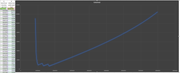
Then I took the slowdown part to estimate the drag factor:

All times are in micro seconds. The drag formula is:
drag = 10^6*MoI*8/(2*pi)*dy/dx = 184
Where:
MoI=0.1 kg m²
8 because I have 8 pulses per revolution
pi= 3.14....
dy= time_between_pulse_end - time_between_pulse_start
dx= time_end-time_start
Data is raw, thus no filter applied. I just sent the variables out on the serial and saved them.
Using this data I compute the speed with the formula:
u = (k/c)^0.3333*w = [m/s]
Where:
k = drag (184)
c = 2.8 (taken from https://eodg.atm.ox.ac.uk/user/dudhia/r ... meter.html )
w = flywheel speed [rad/s]
The problem is that u turns out too big. In fact, considering w = 90 rad/s (a value I measured while rowing smoothly, which seems reasonable), u becomes:
u = (184/2.8)^0.3333 * 90 = 363.13 m/s
which of course is too big. So, since 90 rad/s seems reasonable (I check the frequency of pulses with the oscilloscope just to be 100% sure and I got 9ms period, so 2*pi*1000/8/9 = 87rad/s, the problem is in k/c, I guess. What am I doing wrong?
Nomath, I took the graphs you requested. I recorded the time between pulses versus total time. Here you find 2 strokes and then a natural slowdown until rest.
Then I took the slowdown part to estimate the drag factor:
All times are in micro seconds. The drag formula is:
drag = 10^6*MoI*8/(2*pi)*dy/dx = 184
Where:
MoI=0.1 kg m²
8 because I have 8 pulses per revolution
pi= 3.14....
dy= time_between_pulse_end - time_between_pulse_start
dx= time_end-time_start
Data is raw, thus no filter applied. I just sent the variables out on the serial and saved them.
Using this data I compute the speed with the formula:
u = (k/c)^0.3333*w = [m/s]
Where:
k = drag (184)
c = 2.8 (taken from https://eodg.atm.ox.ac.uk/user/dudhia/r ... meter.html )
w = flywheel speed [rad/s]
The problem is that u turns out too big. In fact, considering w = 90 rad/s (a value I measured while rowing smoothly, which seems reasonable), u becomes:
u = (184/2.8)^0.3333 * 90 = 363.13 m/s
which of course is too big. So, since 90 rad/s seems reasonable (I check the frequency of pulses with the oscilloscope just to be 100% sure and I got 9ms period, so 2*pi*1000/8/9 = 87rad/s, the problem is in k/c, I guess. What am I doing wrong?